 Shows the connection from the purlins to the rafter. You can also see the insulation in this picture.
The connection between the bracing and propping to the concrete tilt-up to the concrete slab.
 In this picture you can see the bracing and propping in full length. The cross bracing in the cieling is connected to the rafter along with the purlins. Again in this photo you can see the insulation.

Again the bracing and propping is evident in this photo but you can also see the girts and how they have been connected to the concrete panel.

You can almost see the full span of the rafters in this picture and how the purlins are connected to them. You can also see the extent of the bracing and propping and how it is needed for each concrete panel. The bracing and insulation in the cieling is also evident.

What the tilt-up concrete panel looks like in full close up view.
 View of the site from the outside.
 Completed warehouse in the neighbouring lot.
 Structural details 1.
 Structural details 2.


 Raft slab layoutplan.

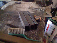 The steel we wanted to use was to long, so we marked out sections and used 2 and a half pieces to get the correct measurements.
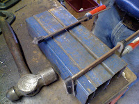
 The angle grinder was then used to cut two pieces of steel to the size above. We then used clamps to keep them together to get the desired thickness before we welded the two pieces together.
 The welding process then began, first the two pieces of steel that were being used for the base plate followed by the two and a half pieces of steel that were being used for the steel reinforcement inside the LVL column.
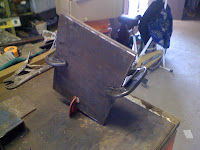
 A small piece of steel was then cut and placed on top of the steel reinforcement before being welded into place. We then marked up the base plate so that the steel would sit exactly in the middle.
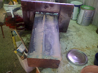 Once the steel was welded a grinder was used to get rid of any sharp edges. We then covered the steel in a plasti-bond filler and sanded it down to fill any holes.
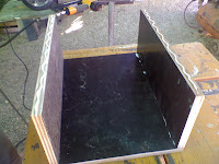 To make the "LVL" column we used several pieces of scrap marine plywood which we cut into pieces then glued and nailed together. Because the steel reinforcement would be going inside the frame we also needed to ensure that it wasn't hollow so we had to fill the frame we had made with extra pieces of timber to make it more realistic.
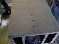 The steel was spraypainted silver to give it a galvanised look and to hide any blemishes that had been caused during the welding etc. The "LVL" column we originally constructed was finished with some natural wood plywood to give it a nicer finish before we began drilling holes into it.
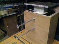 We used the holes on the column to mark off where the holes would need to be placed on the steel then proceeded to drill the holes into place. Holes were then drilled into the base plate and the construction of the section really began. We had to line up the frame with the pieces of timber inside it and the steel to be able to bolt the entire thing together.
 Off-cuts from the natural wood plywood were used to seal the bottom of the column before bolting the base plate to the concrete. The only thing left to do now is varnish the timber.


 Artists impression of the completed project.